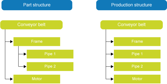
The Part structure form shows the entire structure, including all underlying levels, of the part selected on the Parts form. The part structure serves as the basis for the production structure. This production structure is also displayed on the form when the selected part is linked to a production file. If more than one production file is linked, the default production file is shown: a default production file has the Default check box selected on the Production files linked to parts form.
If you do not want to see the linked production file on the form straight away, deselect the 'Show linked production calculation' option in the Settings menu. This enables the data on the Part structure form to be displayed more quickly. For large production structures, you can select the check box yourself when you want to see the comparison with the part structure.
Differences between the structures
If the part structure differs from the production structure, this is indicated on the form. The differences marked on the form are listed below.
You can choose to display only the differing lines on the form, to make it clear which lines need to be dealt with. To do so, click on the toolbar at the top of the form.
Note: Some differences between the part structure and the production structure can be traced back to the order code of the part.
To some extent, the order code of parts determines which parts are transferred when the calculation is copied from the part structure to the production structure. As a result, the production structure on the Part structure or Production structure form may differ from the part structure without there being actual discrepancies. These differences are therefore not marked as discrepancies on the structure form.
The section below describes the impact on the production structure for each order code when the calculation is copied successfully.
Order code: Produce in new production file
The part structure is identical to the production structure if the order code of parts is 'Produce in new production file', and the underlying parts have the order code 'In stock'.
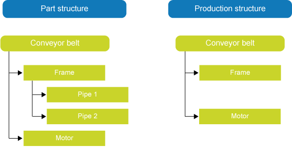
If a part has the order code 'Copy calculation (phantom)', the production structure has a flatter structure than the part structure. In the part structure, the calculation lines are on a level below the part, whereas in the production structure, they are on the same level as the part.
Order codes: Purchase to order, custom; Purchase to order, commercial quantity; In stock; Supplied by customer
Initially, production files for a customer order do not contain any parts with the order code 'Purchase to order, custom', 'Purchase to order, commercial quantity', 'In stock' or 'Supplied by customer'. In some situations, however, a part may initially have had a different order code ('Produce in new production file' or 'Copy calculation (phantom)'), and may be assigned one of the order codes listed at a later stage. In that case, the part structure does contain calculation lines, but the production structure does not.
Imagine the part calculation has already been built and copied to a production file, but the capacity for the production of the part turns out to be insufficient. You ask the customer to deliver the assembled component. You change the order code 'Produce in new production file' into 'Supplied by customer'. The part structure will now show the component with the calculation lines, but the production structure only shows the assembled component.
Line added: If the icon is shown on the left-hand side of the form, the production structure has a line that is missing from the part structure. If the icon is shown on the right-hand side of the form, the production structure has a line that is missing from the part structure.
In the following cases, production calculation lines are not marked as added during production:
The part type is 'Costs' or 'Services'.
The line was created in the actual costing phase.
The line is marked as a 'special BOM part'.
In the next scenario, part calculation lines are not marked as added to the part structure:
Line deleted: The icon indicates that a line has been deleted from the structure that still exists in the other structure.
[Cell color]
Indicates which field differs from the field in the other structure. Discrepancies are identified for the following fields:
Quantity
Length, Width, Height
Waste %
Description
Remark
CAD reference, CAD classification
Unit, Unit code
Line
The discrepancies actually displayed are set on the Compare fields form. Just select the fields for which you want to see discrepancies. This form also allows you to select the color for cells with discrepancies.
Indicates that the structure contains one or more lines that have been changed, added or deleted (see above). The image is also visible for collapsed lines.
Differences between the structures may be caused by:
Changes to the part structure that have not yet been applied to the production structure.
Changes to the production structure that do not originate from the part structure.
 Impact of order codes on production structure