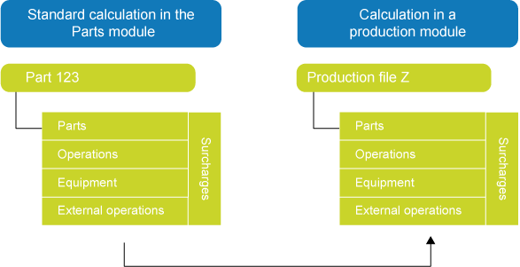
Once you have added a production file to an offer or order, you can add a calculation to the production file, consisting of parts, operations, equipment, external operations, and surcharges. You can choose to add an all-new calculation to the production file, or you can copy an existing calculation, which you then adapt to your requirements. Instead of copying all calculation components, you can also choose to copy only parts and operations from the calculation.
Run the Copy calculation from part to production fileprocess to copy a calculation from the Parts module to a production file. If the source calculation contains any semi-finished articles, it is possible to immediately create production files for the underlying calculations. You can also choose to do this manually at a later stage, however.
Note: The Edit menu of the Production calculation for parts form has two copy processes that are based on this form: Create production file and copy part calculation and Copy part calculation (phantom). You can use these processes after you have added a new production part to a production calculation, and you want to copy its calculation. The order codes of these production parts usually determine how the underlying calculation is copied, but the choice you make in the Edit menu takes precedence. This means that the order code of the production part is ignored if you make a different choice in the Edit menu.
If Copy documents is selected, documents will be copied from parts to production files. Part calculation documents are always copied, even if the Copy documents check box is not selected.
The setting is to be used by organizations using the following working method:
When the calculation of a template part is copied to a production file, a production file structure is created. Any existing documents will be copied from the part to the production file, but no drawings will have been created yet at that time. The production files are used to create an (offer) calculation. Once the engineering process has been completed, the 2D drawings will be linked to the parts. The planner will copy the part calculation file for each production file by using the Copy calculation from part to production file process. At this stage, also the part drawings will be copied to the production file.
If you select this check box, the part will be linked to the production file, and the part calculation lines will be linked to the production calculation lines for parts. The link will enable you to compare the part structure with the production structure. You can compare the structures on the Part structure form or on the Production structure form. The setting is to be used when you want to be able to compare the part calculation with the production calculation after the part calculation has been copied to the production file.
If you select this check box, the part calculation numbering is copied to the production calculation. This allows you to view your production data with convenient line numbers, for example grouped by type of component: mechanical components 10, 20, 30, etcetera, and electric components 110, 120, 130, etcetera.
The setting applies if the part calculation contains phantoms to be exploded in the production calculation. If you select this check box, the line numbers will be renumbered during the process, so that lines belonging to a phantom line are placed immediately below that phantom line. If you leave this check box empty, the numbering will be as follows: the parts on the highest level will be numbered first (10, 20, 30, etc), then the parts on the second highest level, and then the parts on the level below that, etcetera. The lines belonging to the phantom line will then be placed below the last part of the highest level.
Part calculation
Production calculation, lines grouped by level (check box empty)
Production calculation, lines follow phantom (check box selected)
For each calculation line you can choose to display phantom lines on the form. Select the Also number invisible phantom lines check box to include non-visible phantom lines when renumbering the lines:
If you leave this check box empty, only visible calculation lines will be numbered consecutively. The visible phantom lines are taken into account in the numbering, and the non-visible phantom lines are ignored (the non-visible phantom lines are assigned a negative number). You will see a set of consecutive numbers on the form. In the example below, the numbers are 10, 20 and 30.
If you select the check box, all calculation lines are numbered consecutively. If they contain non-visible phantom lines, you will see that numbers are skipped on the form. The non-visible phantom lines are numbered consecutively, but are not displayed on the form. If the calculation contains non-visible phantom lines, you will see non-consecutive numbers on the form. In the example below, the numbers are 10, 30 and 40.
Check box empty
Check box selected
Frame
Frame
10
Pipe, square
10
Pipe, square
-10
Subframe
20
Subframe
20
Pipe, round
30
Pipe, round
30
Pipe, round
40
Pipe, round
Illustration: Numbered calculation with non-visible phantom line 'Subframe'
 Link part and production calculations