The integration between a CAD or PDM application and Isah ensures that the engineering and logistic departments use the same information. Isah data are available in the CAD or PDM application, and buyers and planners have direct access to the material lists. The advantages of maintaining data in one place, rather than in two places, include less work, fewer mistakes, and up-to-date information.
Copying a BOM from a CAD or PDM application to Isah
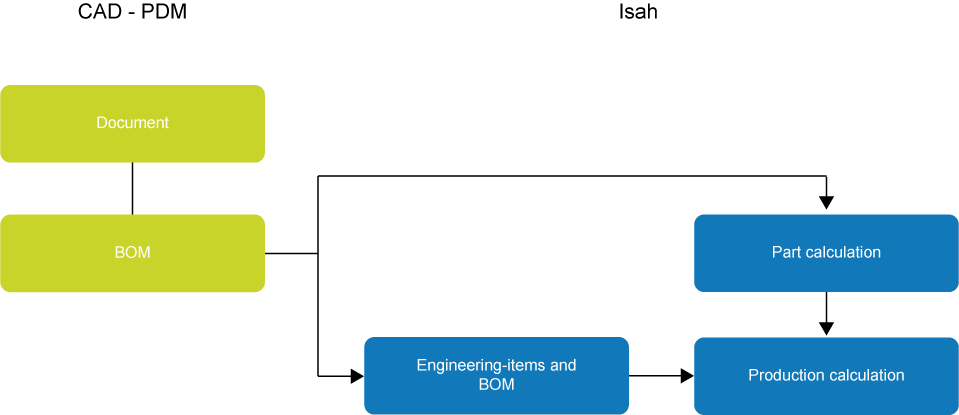
Integration mainly involves copying the BOM from the CAD or PDM application to the production calculation in Isah.
The BOM can be copied:
From the CAD or PDM software to the part calculation, and from the part calculation to the production calculation, for instance in the case of standard parts for which the details are copied to Isah once the engineering work has completed.
From the CAD or PDM software to the production calculation, via engineering items. This method is suitable, for example, for customer-specific products, and if engineering and subsequent processes, such as work preparation and purchasing, take place simultaneously. During those processes, you can allow the Engineering department to make changes to a BOM that is already present in production. In this case, engineering items serve as an intermediate phase when copying data to Isah.
If there is a direct link between the CAD or PDM application and the part calculation, copy the data from the CAD or PDM application to the part calculation in Isah. The settings for this link are defined in the Engineering module (see below).
For links established through engineering items, use the synchronization processes in the Engineering module to copy the data to the production calculation, and define the settings and the engineering items themselves. Engineering items are used to stage the synchronization of external BOMs with a production file. They allow you to decide who can synchronize what and when, and to define the rights required for synchronization. This way, you could, for example, segregate the duties of the engineer and the planner. A structure of engineering items does require additional administrative work, however, as every engineering item must be linked to a part. This means that a part must be present for every engineering item.
Settings for copying data from Isah to a CAD or PDM application
The following options are available for copying information from Isah to an CAD or PDM application:
Document properties: From within Isah, you can create document properties for a great many CAD documents, and fill them with information from Isah. For example, you can specify the company name, so the recipients of the document will know where it came from, or configure that the customer name, rather than the customer code, is shown in the BOM on the drawing.
The contents of the BOM on the drawing. The contents of the calculation (BOM), as registered in Isah, appear on the drawing. You specify the data to be included in the BOM and the order in which they are to appear.
Scenarios for working with engineering and logistics
The engineering integration offers many options to suit the different engineering and logistics processes used in different companies. Specific options can be set for:
Structure: Do you want to copy all or part of the hierarchical engineering structure? Do you prefer a layered structure, or should all or part of the structure be reduced (exploded) to one level?
Level of engineering: Do you want to specify the engineering structure in full, in part or not at all?
Time of release: Should an engineering structure be completed before the BOM is defined in Isah (serially), or at the same time as the BOM in Isah (concurrent)?
Application of materials: How are basic materials or standard components from the symbol library applied?
If an engineer creates a provisional CAD document, for instance of a frame, he can pre-create it in Isah as an engineering item. Once the document is finished, the planner will release the drawing and synchronize it with the production file. It is only then that the document is transferred to production.
The entire engineering BOM is copied to a new production file in Isah. Every engineering item will have a linked production file, and every engineering BOM line will become a production calculation line in Isah. If the production calculation line contains a part with the order code 'Produce in new production file', a new production file will be created, and also its BOM will be copied.
If in Isah all or part of the production file has already been created for the relevant part, the production file will be modified in the engineering BOM during synchronization.
If an engineering BOM containing a great number of semi-finished articles is copied in its entirety to a new production file in Isah, you could end up with a large number of production files. To work with a flatter structure in production, explode the engineering BOM. On the engineering BOM line, you can set the line to be exploded during synchronization with production. The calculation lines of a semi-finished product will then be displayed on the same level as the semi-finished product itself. You can choose to display the semi-finished product in the calculation as a phantom line, so you can see the product the calculation lines correspond to.
Example
An office furniture manufacturer manufactures various types of tables. The table legs are always attached using one bolt, one nut, and two locking rings. One table with four legs therefore requires four bolts, four nuts, and eight locking rings. These items are included in the phantom part called 'Fastening Set'. When entering one set in a production BOM, three calculation lines are copied for the bolt, nuts, and locking rings.
Typically, an engineer will draw the required components first, then the semi-finished products, and lastly the end product. The engineering for long lead-time purchase items often gets priority. In that case, you will want to release components for which engineering is complete, and start the production. The location of this component in the ultimate calculation is not yet known at that time, however. Such a production order will already be linked to the sales order at this stage, and will get its final destination at a later time.
An engineering BOM is likely to change after the BOM (or part of it) has been linked to a production file. The following situations may occur:
Features, such as the quantity or the size, have changed. It depends on the settings whether the linked calculation line is modified.
The structure has changed. In this case, any additions will result in new calculation lines. If a BOM line is deleted, the link between that line and the calculation line will be removed. Depending on the settings and conditions, also deleted lines will be removed from the calculation.
Some companies engineer to customer order, for which products are delivered in stages. Engineering will review the lessons learned during the first production runs, and then modify the remaining production orders accordingly. In this case, you will link multiple production orders to each engineering item.
A 3D model can contain multiple identical parts. If these parts are used in various places in the model, each part will get its own production file. As the parts are identical, you will want to have them in one production file, however. You note the number of parts, so that after synchronization, you can enter this number in one of those production files and delete the other production files.
If you are working from a library, and the engineering BOM is copied, all library items must be added as engineering items. Most standard parts in the Parts module must therefore be added as engineering items.
If you want to link to both parts and production files, the standard parts must be entered as engineering items. Then you add them to a production file.
Integration with 2D or 3D CAD software
The integration with a 2D CAD application differs greatly from the integration with a 3D CAD application. In 3D CAD applications, the engineer creates a document for all components, and combines the related components in an assembly document. This way, a hierarchy of documents is created, and this hierarchical structure serves as a model for the calculation in Isah. Most 2D CAD applications lack such a structure, which means that the calculation (BOM) must be defined in Isah.
 Creating an engineering item for a provisional CAD document